Keil5中找不到外设函数
相关链接
stm32f10x_it.c、stm32f10x_it.h和stm32f10x_conf.h文件作用
问题描述
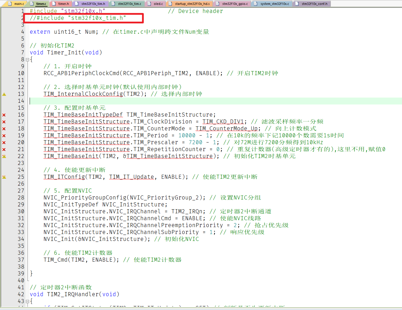
在编写外设函数中,如果没有包含对应的头文件,而只包换stm32f10x.h文件则会出现索引不到的问题
如下图所示,在编写定时器相关函数中,注释掉#include "stm32f10x_tim.h"则会出现编译错误
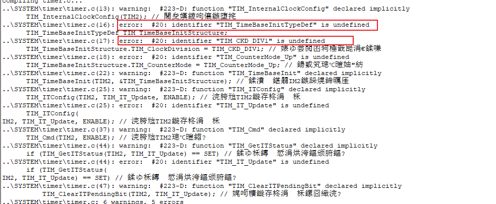
报错信息如下图所示
解决方案
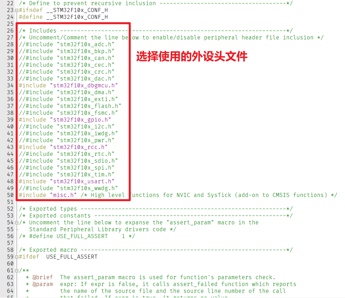
引用stm32f10x_conf.h文件,并在该文件中添加需要的外设函数头文件,如下图所示
stm32f10x_it.c、stm32f10x_it.h和stm32f10x_conf.h文件作用
在编写外设函数中,如果没有包含对应的头文件,而只包换stm32f10x.h文件则会出现索引不到的问题
如下图所示,在编写定时器相关函数中,注释掉#include "stm32f10x_tim.h"则会出现编译错误
报错信息如下图所示
引用stm32f10x_conf.h文件,并在该文件中添加需要的外设函数头文件,如下图所示
相关问题部分截图如下:
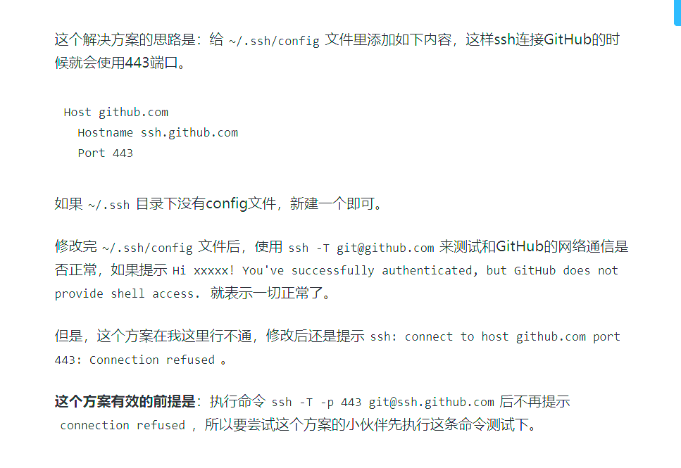
本地仓库在推送到github远端仓库时出现报错如下
1 | > git pull --tags origin main |
新建~/.ssh/config文件, 写入如下内容
1 | Host github.com |
保存后问题解决
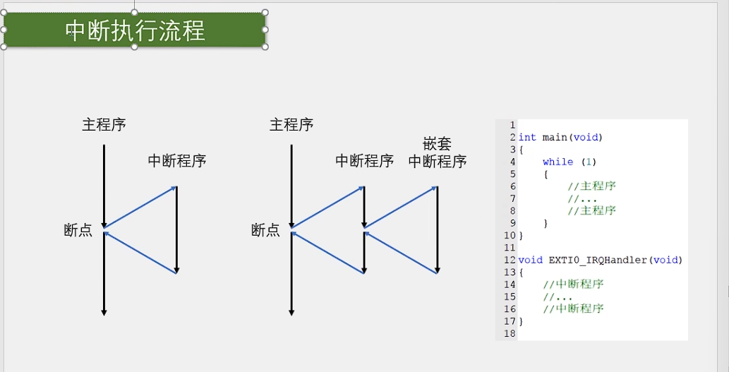
中断: 在主程序运行过程中,出现了特定的中断触发条件(中断源), 使得CPU暂停当前正在运行的程序,转而处
理中断程序,处理完成后又返回原来被暂停的位置继续运行.
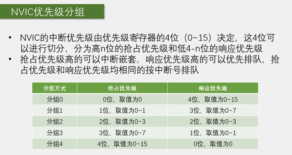
中断优先级: 当有多个中断源同时申请中断时,CPU会根据中断源的轻重缓急进行裁决,优先相应更加紧急的中断源.
中断嵌套: 当一个中断程序正在运行时,又有新的更高优先级的中断源申请中断,CPU再次暂停当前中断程序,转而处理新的中断程序,处理完成后依次进行返回.
中断执行流程图如下图所示:
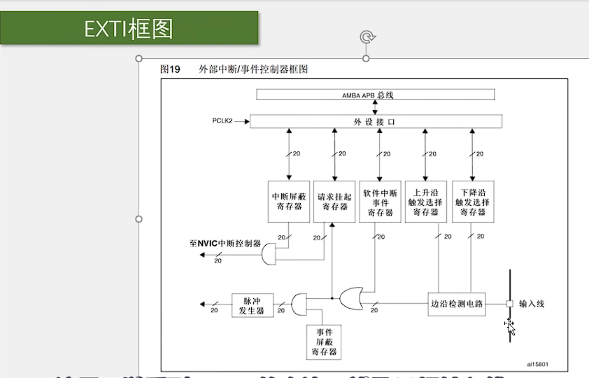
外部中断(External Interrupt)是指来自外部设备或信号的中断请求。
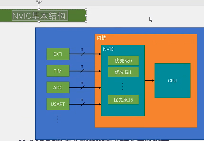
EXTI可以监测GPIO口的电平信号,当其指定的GPIO口电平发生变化时,EXTI将立即向NVIC发出中断申请,
经过NVIC裁决后即可中断CPU主程序,使CPU执行EXTI对应的中断程序.
支持的触发方式有:上升沿/下降沿/双边沿/软件触发。
支持的GPIO口: 所有GPIO口均可触发外部中断但是相同的Pin不能同时触发中断(如PA0和PB0不能同时触发中断).
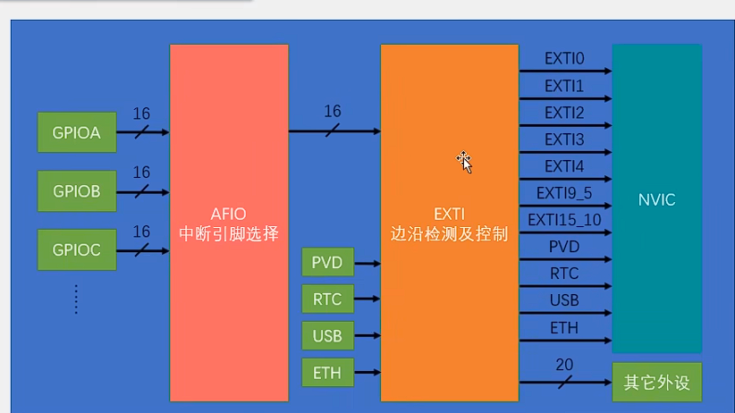
通道数: 16个GPIO_Pin,外加PVD输出,RTC闹钟,USB唤醒,以太网唤醒.
触发响应方式: 中断响应/事件响应(用来触发其他外设的事件).
AFIO结构图如下:
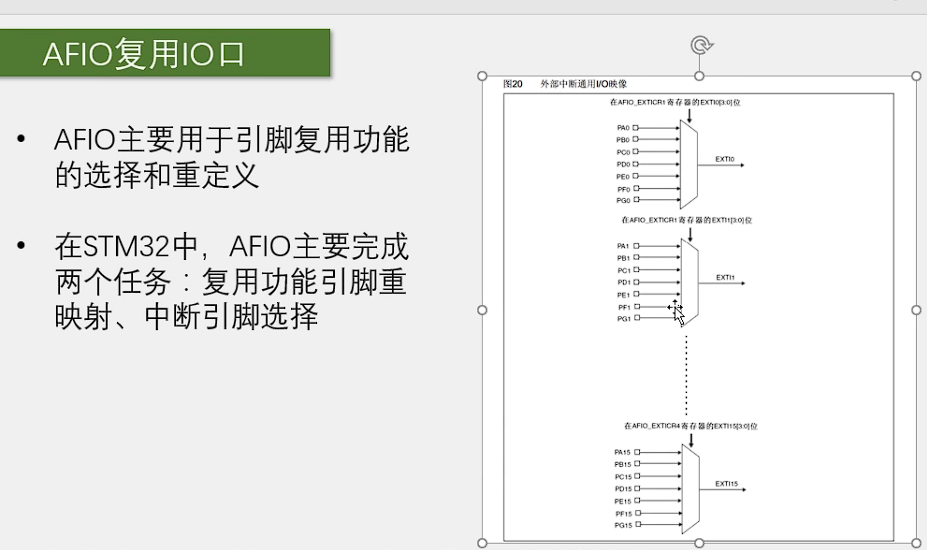
通过数据选择器来将PA0~PG0选择其中一条线到EXTI0.
EXTI框图如下:
工程文件目录: 5-1 EXTI中断火焰监测
实验目标: 使用火焰传感器监测火焰并通过OLED屏显示火焰警报
OLED连接
火焰传感器连接
实物如图所示
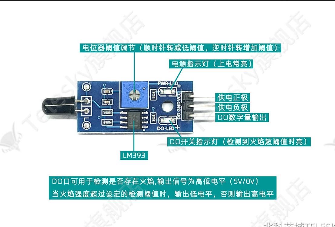
资料链接 : 火焰传感器链接
传感器型号: 3针版
当火焰强度超过阈值时,输出低电平,否则输出高电平,所以需要配置为下降沿触发
在fire.c文件中编写如下代码
1 |
|
在fire.h文件中编写如下代码
1 |
|
在main.c文件中编写如下代码
1 |
|
新建Hardware文件夹来存放驱动文件
其中LED.h和LED.c为LED的驱动文件
LED硬件电路如下图所示
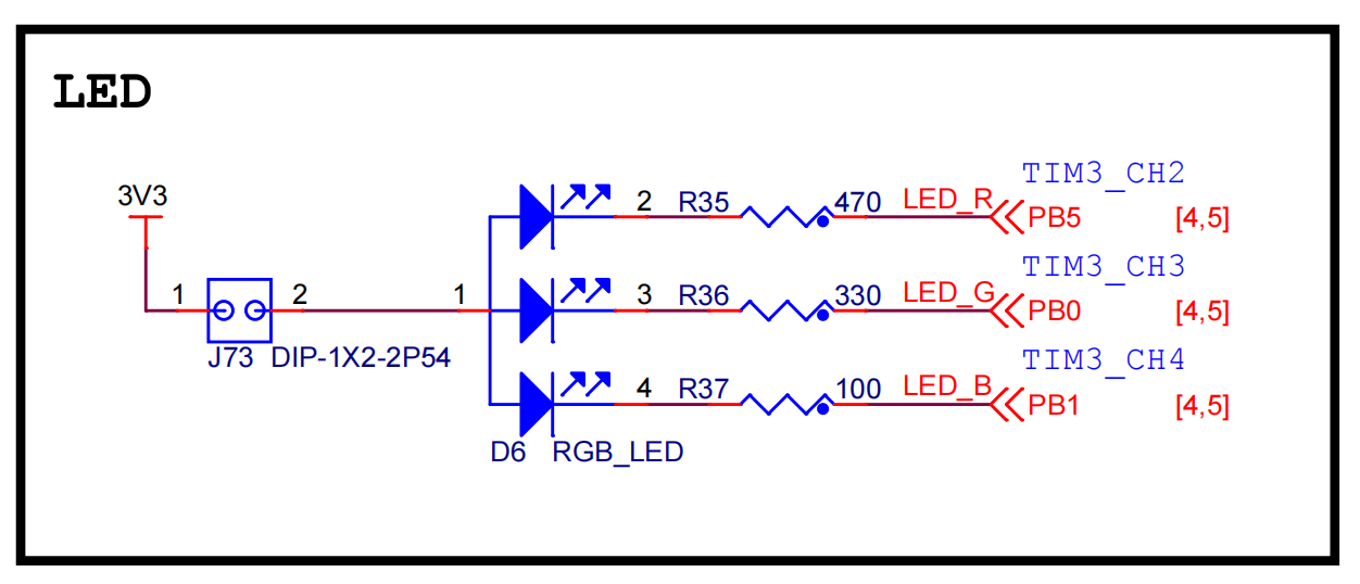
在LED.c中定义红色LED的驱动函数
1 |
|
按键接在PA0引脚, 按键按下PA0为高电平
按键的硬件连接图如下图所示
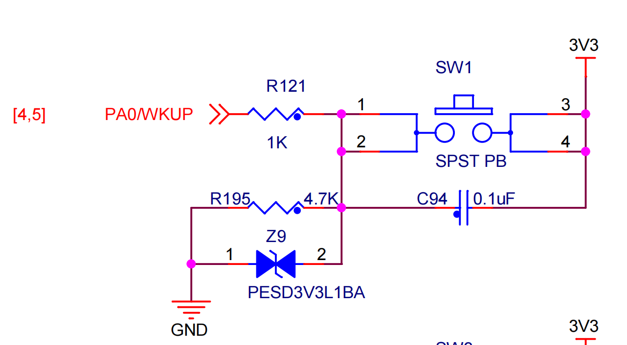
配置PA0引脚为下拉输入模式
在KEY.c定义按键的驱动函数
1 |
|
在KEY.h中提供函数接口
1 |
|
执行流程
main.c中定义全局变量KEYNum用来存储按键状态在main.c中实现主控制流程
1 | /* |
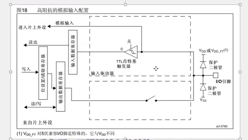
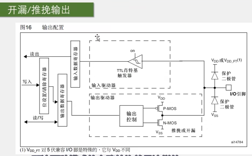
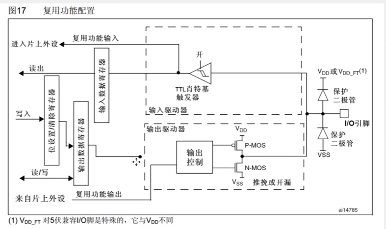
共八种输入输出模式,引脚电平为0V~3.3V, 部分引脚可容忍5V电平。
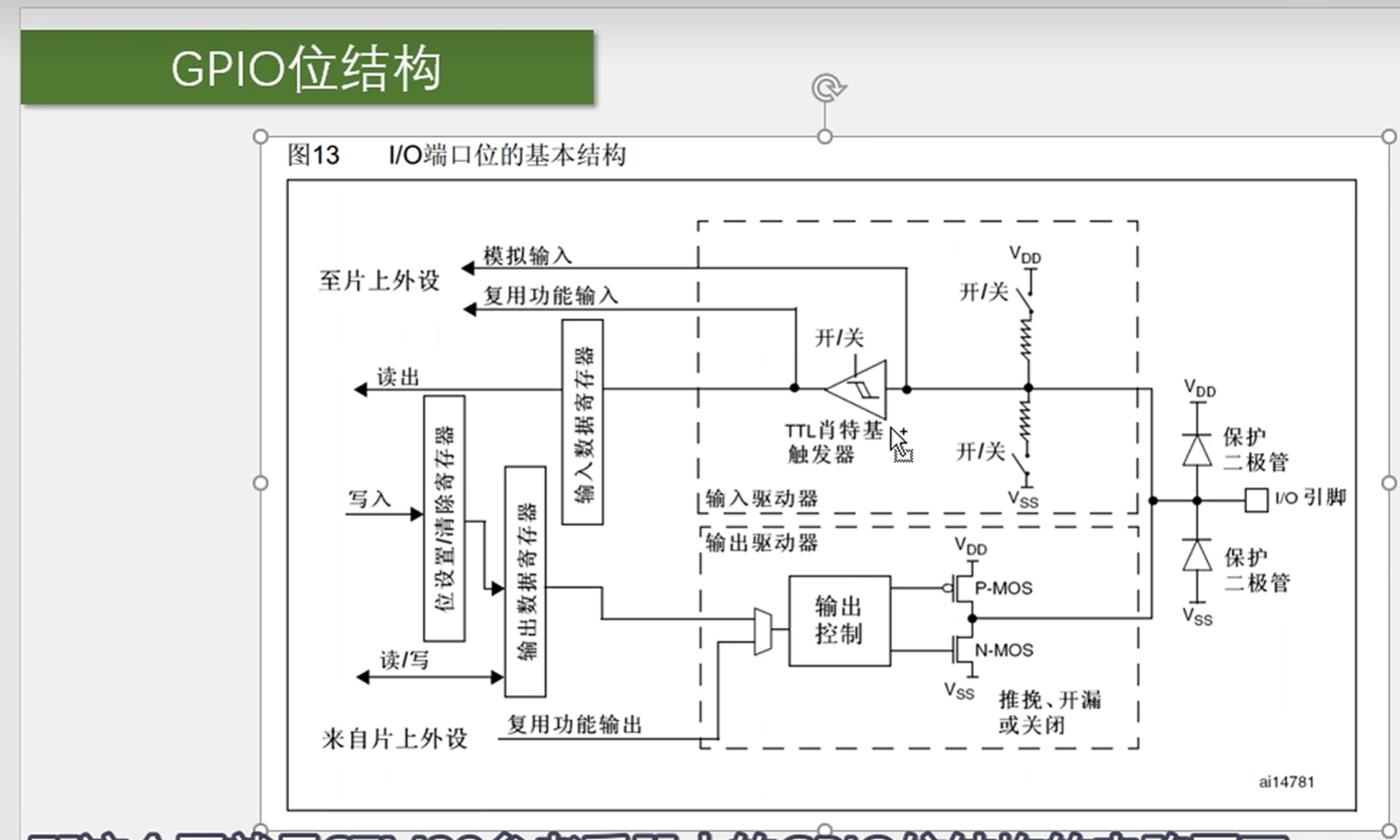
IO引脚(0~3.3V)
输入驱动器
输出寄存器
GPIO模式
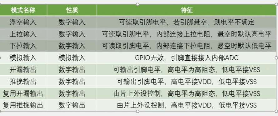
浮空/上拉/下拉输入
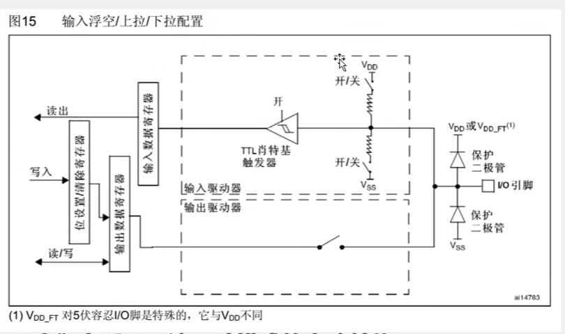
模拟输入
开漏/推挽输出
复用开漏/推挽输出
工程文件目录: 3-2 GPIO输出-LED闪烁
使用GPIO输出高低电平,控制LED灯的亮灭。
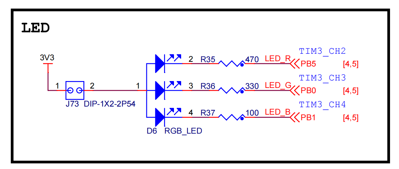
LED红绿蓝均为低电平点亮,红灯接PB5,绿灯接PB0,蓝灯接PB1。
PB5(红灯)为GPIO输出模式,推挽输出模式。低电平点亮。
添加系统延时模块在System文件夹下
Delay.c中定义
1 |
|
Delay.h中声明
1 |
|
在主函数中控制LED闪烁
代码如下
1 | /* |
1 | nmp install -g hexo-cli |
在你想要创建博客的目录下执行以下命令:
1 | hexo init |
这会在当前目录下创建一个新的hexo项目。
常用命令
1 | hexo new "post title" # 创建一篇新的文章 |
仓库名为username.github.io,其中username为你的github用户名。
1 | npm install --save hexo-deployer-git |
修改_config.yml文件,修改以下内容:
1 | # Deployment |
此时使用 hexo d 即可将博客部署到github上。
在hexo目录下执行以下命令来安装next主题:
1 | npm install hexo-theme-next |
1 | npm install hexo-theme-next@latest |
1 | # Installed through npm |
打开_config.yml文件,修改以下内容:
1 | theme: next |
打开_config.next.yml文件,修改以下内容:
1 | # Allow to cache content generation. |
在根目录下输入
1 | hexo new page tags |
默认在source\tags\index.md中创建
修改index.md文件,添加以下内容:
即添加type: “tags”
1 | --- |
修改_config-next.yml文件,修改以下内容:
1 | # themes\scallop\_config.yml |
在文章中添加tags标签即可
1 | --- |
1 | npm install hexo-generator-searchdb |
打开_config.yml文件,添加以下内容:
1 | search: |
打开_config.next.yml文件,添加以下内容:
1 | # Local search |
登录LiveRe并安装
安装完成后找到data-uid
复制data-uid = 后的内容
打开_config.next.yml文件,添加以下内容:
1 | # Support for LiveRe comments system. |
fancybox和mediumzoom不要同时启用
1 | # Easily enable fast Ajax navigation on your website. |